Category: Engineering

Eddy current braking

Eddy current braking

Eddy current braking

08/02/16

“How can we apply the theory of eddy currents to transportation?”

What separates scientists and engineers is very simple, scientists discover new phenomena about the natural universe, while engineers take this knowledge and apply it to accomplish something useful. For example, scientists might discover that a specific current forms when conductors had a changing magnetic flux is applied to it, and name it something like eddy current. Now, how could an engineer take a phenomena like this and make it do something productive for humanity?

Well, let’s think about it like an engineer. We know that this current occurs because of an external magnetic field. Furthermore, we know that when current interacts with an external magnetic field, a perpendicular force is formed on the medium of the current. So let’s go further and think about we can do with this force. Well, a force can oppose motion, so how about we take this physical phenomena and apply it to an area that involves motion, namely transportation.

Let’s suppose that we have wheels made out of a conductive material, and that these wheels are moving at a certain RPM. If we take a magnet, and put the wheels in between both poles, then the constantly moving wheels will experience a constantly changing magnetic flux since parts of the conductor will always be moving into and out of the field. This will in turn generate an eddy current, which will produce a force that opposes the motion of the wheel, which in turn will cause it to slow down and brake. Engineers have termed this mechanism eddy current braking. Eddy current are so popular that they are used in many different cases, whether it be recreational gym equipment or high speed electric trains!

Hallback array

Hallback array

Hallback array

08/01/16

“How can we create a one-sided magnet?

We have a problem. Suppose that we want to create a magnet, but with one very simple yet very difficult constraint, we want the magnetic field to be only present on one side.
Now that we have decided on the requirements, let’s use our engineering abilities to bring this idea into reality. Our main problem is that magnets fields are usually symmetric on both sides because the polarity of the entire material points in the same direction. Now, how can we get around this physical phenomena to acheive our goals? Well, luckily for us, there is another facet of magnets that could be quite cordial to our goal if applied correctly. If two magnetic fields interact with eachother and go in oppossite direction, then there would be a cancellation of force. Now, what if instead of having one continuous material with each part having the same magnetic direction, we were to fasten discrete blocks together, with each the polarity of each block being 90 degrees perpendicular to the block before it? With this method, the magnetic fields on one side of the blocks would cancel out while the fields on the opposite side would super-combine, giving us a nearly one sided magnet if the this pattern repeats. Scientist and Engineers have termed this type of arrangement a hallbach array. Believe it or not, you probably see hallbach arrays everytime time in the morning, as hallbach arrays are what what makes refridgerator magnets work!

Brushless motors

Brushless motors

Brushless motors

07/18/16

“Is it possible to have an electric motor without a brush?”

The workings of most DC motor systems are simple and efficient, but with one serious flaw, their brushing infrastructure.

What does this mean?

Well,lets first look at how a D.C motor works. A circular structure of permanent magnets create a magnetic field, and an electromagnet based central rotor will interact with this magnetic field when current is applied to it. This magnetic field will be able to flip the rotor 180 degrees, by which time the polarity of the electromagnet must change to continue. This is accomplished by a mechanical brush located at the center of the rotor. Even though this brush is absolutely necessary for the electric motor to work, it comes with some large drawbacks. This added machinery effectively limits the speed of the motor, is very prone to wearing out (which makes upkeep much more expensive), and makes the temperature much harder to cool.

The solution? How about turn the whole machine inside out! By placing the electromagnets on the outside and the permanent magnets on the rotor and using a computer system to control everything, the motor will have a momentous increase in power generation. Engineers have termed this type of motor an electric motor.

Synchronous vs induction mechanisms for linear motors

Synchronous vs induction mechanisms for linear motors

Synchronous vs induction mechanisms for linear motors

Isaac Gendler

07/17/16

“What are the benefits and drawbacks between the two different types of linear motors?”

Thanks to the constant ingenuity of humanity, it turns out there is not only one way but actually two ways to design a linear motor! The separate cases are know as the Linear induction motor (in which the changing magnetic field of the primary outpaces the one of the secondary) and a linear synchronous motor (In which the magnetic field field of both the primary and the secondary match-up).

Linear induction motors have numerous advantages. First of all, the construction of such systems have a similar layout to existing electric railway infrastructure, making it easier to integrate into an older system.  The track for the LIM is also very simple, making it easier for vehicles of all different shapes and sizes to be integrated. However, induction based technology has a lower efficiency than not only synchronous motors but normal rotary motors as well! In addition, LIM systems have higher weights, which limits their maximum travel speed and carrying capacity!

Luckily, we have more than one option when deciding to use linear motor technology. Linear synchronous motors use lighter-weight technology, which allows for higher speed and cargo levels. The disadvantages of such systems is that exact data is required for monitoring the magnets (to make sure that they are within sync with the LSMs). This results in a much more complicated design for maintaining the guideway. As each train on the platforms must be individually analyzed, a lower train density ensues. Since LSMs are designed to be completely in sync with the magnets, even very small impingements on the systems could result in drastic consequences.

In summation, Engineers have many choices for what type of linear motors they select.

AC motors

AC motors

AC motors

07/15/16

“How can we apply AC electricity to motor technology?”

Motors are undoubtedly one of the most useful inventions by humanity. However, how can we integrate this concept with AC electricity? Well, let’s build such a machine in our mind first. This machine will have two primary parts, a stationary stator and a rotary rotor.  The stator consists of a series of highly permeable steel laminations cast inside a circular frame. Winding will pass through this stator, and when AC current is passed through this winding, an electromagnetic field will be formed. This current will go in three phases, so each starts at a different third of the AC cycle, and because of these three different phases, a constantly rotating magnetic field will be formed. A conducting cage will be housed inside the stator to act as a rotar. Since conductors experience a force when exposed to a constantly changing magnetic field, the rotor will begin to rotate, causing mechanical power to be generated. The Speed of the rotor is called the rotor speed, and the speed of the magnetic field is called the synchronous speed. Due to the laws of physics, the rotor will never be able to catch up to the synchronous speed.


Linear motors

Linear motors

Linear motors

07/14/16

“What would happen if you made a machine by unfolding a rotary motor?”

Let’s suppose that we want to move something in a linear direction in a highly efficient manner.  What if we took a rotary motor, and unfolded the shell so it would move in a linear direction? Believe it or not, not only does this work in theory, but it has been accomplished before. Engineers have termed this mechanism a linear motor.

To get the big picture, the linear motor works as follows; A square forcer will include an iron core and a thermal protection device. This forcer will rest on a stator will encase magnets, electric wires, a base, and a shield. A Linear guideway will be placed in between the forcer and the stator to allow for movement of the former. The forcer will be housed in forcer plates, and finally a position encoder will be attached to provide feedback on the position of the linear motor. The forcer moves because the controller will provide a constantly changing current at different times to the windings, which in turn will interact with the conductive rotor, causing a magnetic force on the forcer, which will move the rotor at very high speeds.

Linear motors are very pragmatic for many uses. Linear motors have no wearing parts, which makes them faster to build, have longer life cycles, have more efficient temperature control, have higher velocities, and much less polluting to maintain. Linear motors are often applied for industrial, servomechanism, and transportation purposes. Countries such as Germany, Japan, China, the , and the USA are currently using or considering linear motors for transportation purposes.


Air compressors

Air compressors

Air compressors

07/12/16

“Is it possible to store potential energy into pressurized air?”

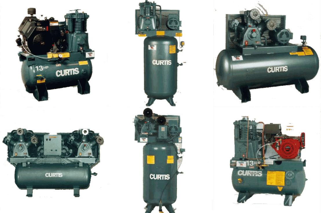
Human society requires energy to be stored in various of forms. Wouldn’t it be useful if we could store all of that potential energy in pressurized air? Well, thanks to civilization’s ingenuity, air compressors have been invented to do that. Air compressors come in two types: positive displacement (which forces air into a chamber which decreases in volume to compress the air) and dynamic displacement (Which uses rotating machinery to impart kinetic energy on to the air). There are many forms of the positive displacement, such as a piston type (Which uses a kinetic energy from a piston t store compressed air), rotary screw compressors (which uses positive displacement that matches two helical screws and guides air into a chamber), and vane compressors (Which uses a slotted rotor with a variable blade placement to guide air into a chamber and compress the volume). Air compressors are often used to work with jack hammers and rotary screws.

Welding

Welding

Welding

07/11/16

“How can we make a high strength connection between two mechanical parts using heat?”

When trying to mate two parts, engineers often run into an issue. Sometimes, conventional methods such as brazing and soldering are not enough, and a more powerfull process is required. However, thanks to the ingenuity of humanity, a new process has been made to solve this road-block. What if we took the two conjoining surfaces, melted them a bit, and then attached the two heated areas together? Not only is this process very effective, but it also very convenient. Scientists and Engineers have termed this process welding. There a many types of welding

One possible methods of welding uses an electrode (a welding rod) to carry electric current to weld the metal. The wire for the electrode is covered in flux for protection, and an electric arc is created along the electrode the melt the metal, generating temperatures of nearly 3600 degrees Celsius!. In addition to the high intensity heat, the subject metal is shielded to be protected from reactive elements in the atmosphere. This process has been termed Shield Metal Arc Welding. This method is often used in steel erection, heavy equipment repair, construction, and pipeline welding. The advantages of using SMAW is that it’s portable, low cost, has no need for a shielding gas and can work on unclean materials, while the disadvantages are that it requires a high level of skill to use, generates a large amount of waste and does not work on thin metals.

Another welding method can be achieved by using a non-consumable tungsten electrode to heat the base metal and create a molten puddle, all while being protected by a shielding gas. This process has been termed Gas Tungsten Arc Welding, since both gas and tungsten are used in this process. The common applications for this method is aerospace welding, piping systems, and motorcycles. The advantages of this method include the fact that it produces clean, high quality welds, it can weld very thin materials (in contrast to SMAW welding), It can fuse a large number of alloys, it creates splatter free weld, and has highly aesthetic weld beads. The drawbacks of using  GTAW is that it requires high operator skill, it is very costly, has lower deposition rate, needs an external gas, and materials must be completely clean.

Next up, is an interesting combination of the above mentioned methods. This method uses a continuously fed electric current to melt a joint (like the SMAW), while being protected by a shielding gas (like the GTAW). This process is known as Gas Metal Arc Welding. GMAW is often applied to small to large manufacturing, auto-body uses, and fabrication. The strengths of using this process include being very efficient (therefore producing little waste), needs lower heat inputs, a minimal weld cleanup, and being comparatively easy to learn. The drawbacks of using this method include a requirement for a shielding gas, having limiting positions, high equipment cost, can not wield thick materials, and material must be free of dirt and the like

The final process is very similar to GMAW, but with one fundamental difference: it uses a tubular filled wire filled with flux instead of a solid wire. Engineers have termed this process Flux-Cored Arc Welding. This method comes in two variants, self-shielding which only uses the flux to protect the arc with no gas and dual-shielding that uses both the flux and the gas. FCAW can often be found being used with thick materials, steel erection, and heavy equipment construction or repair. The strengths of this process include a higher electrode efficiency, lower heat inputs, minimal weld cleanup, reduced welding flames, and no need for external shielding gas. However, the drawbacks of this system must be discussed, as it creates slag, is not recommended for thin materials, generates a lot of smoke, and has a high price tag for the equipment

All in all, welding is a fascinating and diverse process that has implementations in many disparate possibilities.

Atomic clocks

Atomic clocks

Atomic clocks

07/10/16

“Is it possible to have clocks accurate to a billionth of a second?”

We use clocks to keep time everyday. Whether it be for scheduling flights or processing the internet, civilization depends on clock technology to keep everything in balance. Clocks work by measuring the oscillations of a pattern, such as measuring how long a pendulum takes to swing back and forth or the earth to move around the sun. However, such machines are not always perfect. Since clocks (of all types) are physical objects, they are subject to the physical laws of the universe. Consequentially, these contraptions are prone to perturbation, which in effect makes them liable to becoming out of sync with other clocks. These inconsistencies add up over time (pun defiantly intended), and if they go on for too long, then drastic consequences can happen. For example, high speed finance trading could go asunder, which would have devastating effects on the global economy.

So how can we make a clock so accurate that we would never have to worry about civilization collapsing?

Well, luckily for people anxious about such an event, scientists and engineers have constructed marvelous devices known as atomic clocks. Atomic clocks work by measuring the internal oscillation of a cesium atom. Cesium atoms vibrate over 9 billion times in one second, and atomic clocks base their own measurements off such vibrations. Atomic clocks that are so accurate that commercial units are accurate to one second in 3 million years! Because of this genius design, scientists and engineers now base the unit of the second is based upon how  atomic clocks can measure the osculation of a cesium atom.